Entrance counter POC with Windows 10 IoT Core, Raspberry Pi2 and PIR sensors
This tiny project was originally want to showcase how can we use Raspberry Pi2, Windows 10 IoT Core and PIR sensors to count the visitors enter the exhibition hall.
The first showcase was perform during KL Converge 2015 which held on August 27 – 29, 2015 at Kuala Lumpur Convention Center. The second demo of this project is on 2015 Microsoft Malaysia Channel Partner Conference at Sunway Pyramid Convention Centre.
During the first showcase, we are using Intel Galileo Gen 2 with Windows 8.1 and ONLY collect the entry data at main exhibition hall entrance. Whereas, we are now using Windows 10 IoT core on Raspberry Pi2 to collect the entry and exit data on Microsoft Malaysia Channel Partner Conference 2015.
In this article, I would like to share the design of the sensors and the code for Raspberry Pi2.
Components:
- 1 x red LED
- 1 x green LED
- 2 x 330Ω resistors
- 1 x PIR sensor
- 1 x breadboard and serveral male-to-female connector wires
- 1 x Raspberry Pi 2 with loaded Windows 10 for IoT (If you want to know how to provision the Windows 10 for IoT to your Raspberry Pi 2, you can refer to this article
Hardware Setup
Let’s start by wiring up the components on the breadboard as shown in the diagram below.
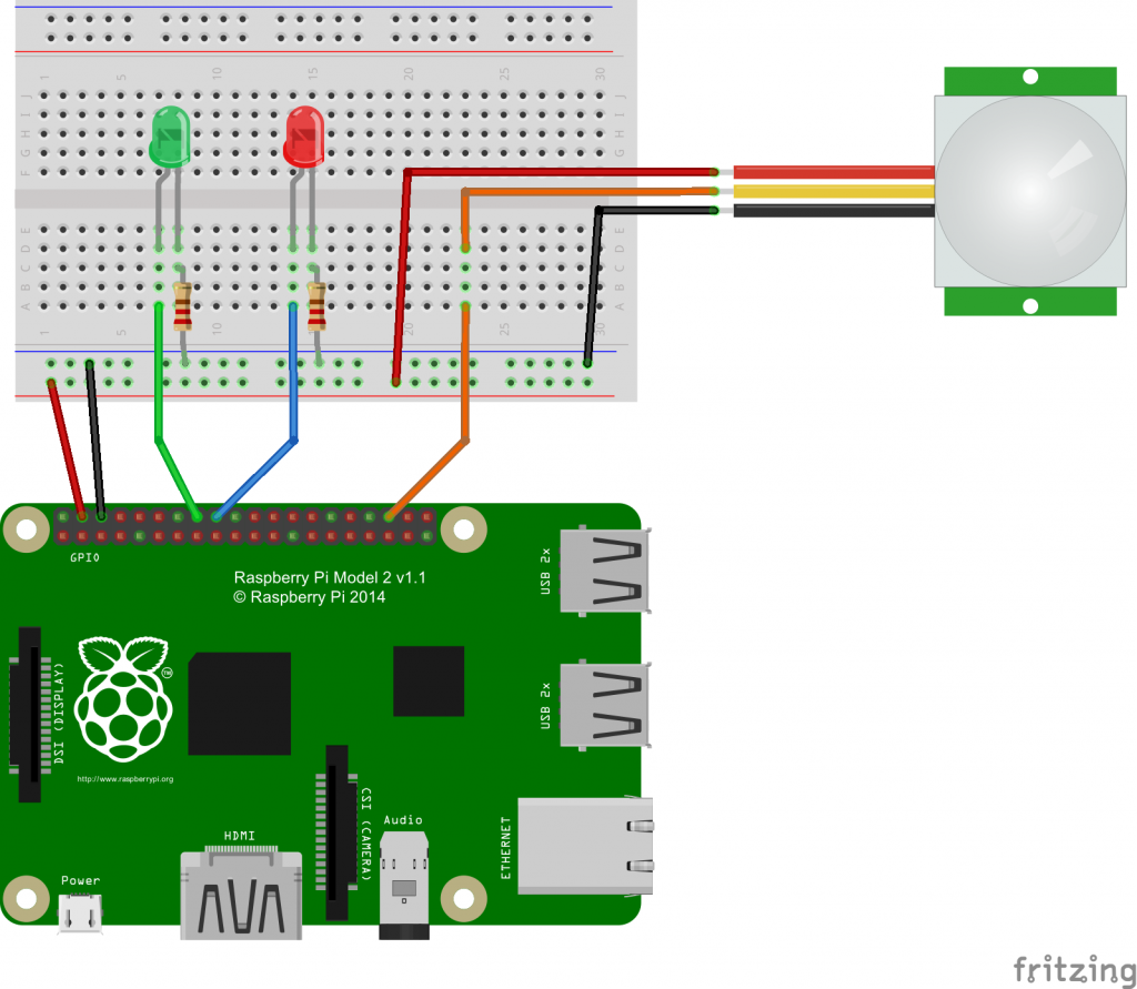
- Connect the cathode of the LEDs to the Ground rail of the breadboard using 330Ω resistors respectively.
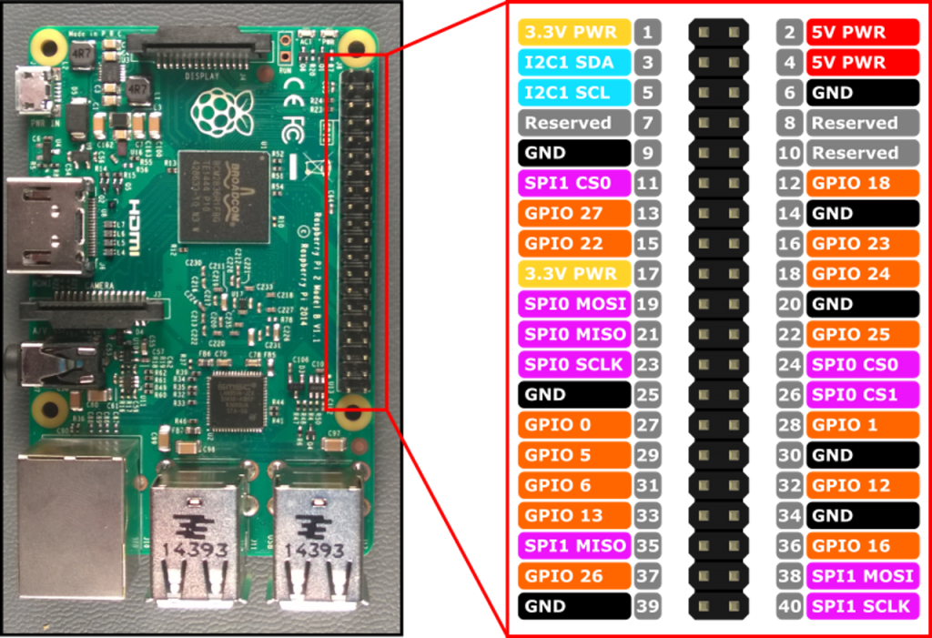
- Connect the anode of the Green LED to Pin 16 (GPIO 23) for Red LED, Pin 18 (GPIO 24) for Red LED and Pin 36 (GPIO 16) to PIR sensor.
- Pin 4 (5V) connect to power rail on the side of the breadboard.
- Pin 6 (GND) connect to ground rail on the side of the breadboard.
Create Sample App
The code in this sample does the following things:
- Initializes the Raspberry Pi 2 GPIO pins
a. Turn system read LED ON (Green LED) - Responds to PIR sensor input
a. While active, turn activity LED On (Red LED)
Add content to MainPage.xaml.cs
Before we add any code to MainPage.xaml.cs, we need to add Windows IoT Extension to our reference.
- In Solution Explorer, right click on References and select Add Reference…
- In the Reference Manager windows, click the arrow next to Windows Universal then click on Extensions
- Check the box next to Windows IoT Extension SDK and click OK
Add the following line at the top of MainPage.xaml.cs
using Windows.Devices.Gpio;With the references added, let put in the code.
The method of InitGPIO() does the following thing:
private void InitGPIO()
{
    gpio = GpioController.GetDefault();
    if (gpio == null)
      return;

    sensor = gpio.OpenPin(16);
    sensorstatus = gpio.OpenPin(24);

    systemstatus = gpio.OpenPin(23);

    sensor.SetDriveMode(GpioDriveMode.Input);
    sensorstatus.SetDriveMode(GpioDriveMode.Output);
    systemstatus.SetDriveMode(GpioDriveMode.Output);

    sensorstatus.Write(GpioPinValue.Low);
    systemstatus.Write(GpioPinValue.High);
}- Initialized GPIO pins that going to use.
- Detect the presentation of GPIO.
When sensor value changed, the following code will execute:
private void Sensor_ValueChanged(GpioPin sender, GpioPinValueChangedEventArgs args)
{
    GpioPinValue value = sensor.Read();

    If (value == GpioPinValue.High)
    {
        // do your work
    }

    While (value == GpioValue.High)
    {
        sensorstatus.Write(GpioPinValue.High);
        value = sensor.Read();
    }

    sensorstatus.Write(GpioPinValue.Low);
}- Turn the activity LED ON when movement detected.
Build, Deploy and have Fun!
Let’s build, deploy and run the app on Raspberry Pi 2.
You can refer to this article to learn how to deploy the app to Raspberry Pi 2.